COMPONENTS / ENGINEERING INTERFACES
Component families for intelligent equipment.
Our quoted lines are motion, power and interconnect, including specified commercial-vehicle electrical interfaces. Cable duty is an installation condition; auxiliary power is a rail requirement. Complete controllers, battery systems, navigation and software are outside the quoted line. AC-DC applies only to plugged-in equipment.
Choose the component or interface.
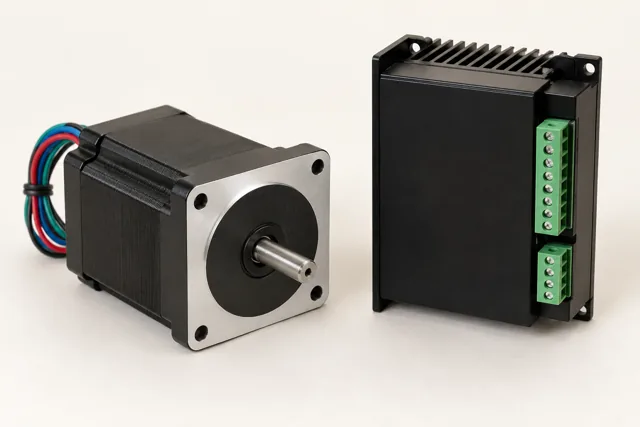
Single-axis stepper & drive
Holding load; running torque at speed; supply and phase current; step/direction or supported command interface.
Requirements & interfaces ↗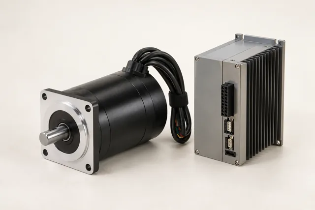
Brushless motor & drive
Wheel or cutter torque; speed range; full supply envelope; continuous and peak duty.
Requirements & interfaces ↗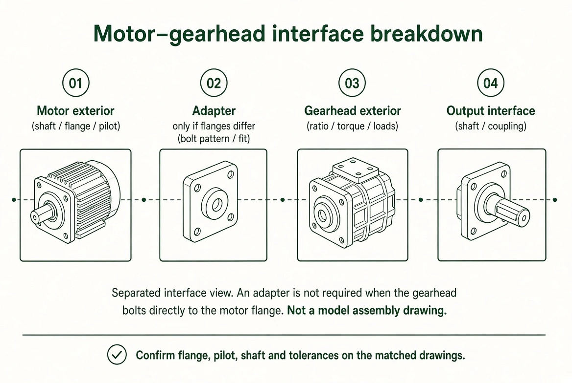
Planetary gearhead
Flange, pilot and shaft; reduction ratio; continuous and peak output torque; radial and axial load.
Requirements & interfaces ↗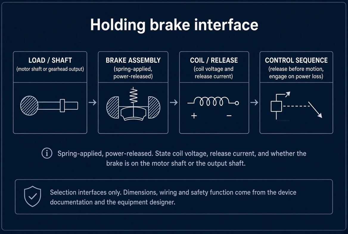
Holding brake
Coil voltage and release current; holding torque; engagement/release time; power-off or power-on action.
Requirements & interfaces ↗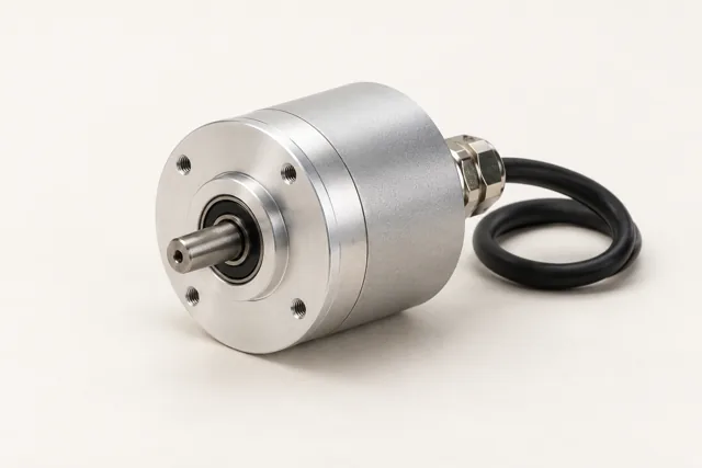
Incremental encoder
Counts per revolution and counting convention; supply; electrical output and frequency; shaft or hub mounting.
Requirements & interfaces ↗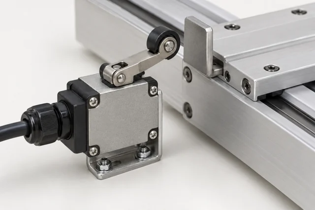
Limit & home devices
Travel and reference locations; supply/contact type; receiving input; installation and operating exposure.
Requirements & interfaces ↗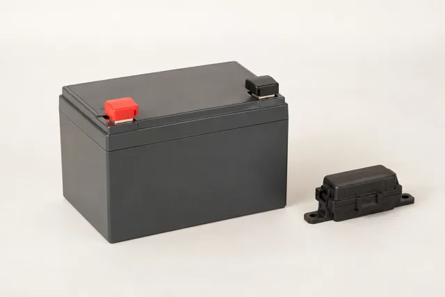
Battery input & protection
Loaded and charged pack range; continuous and peak current; inrush/reverse protection requirements; disconnect and live-mating conditions.
Requirements & interfaces ↗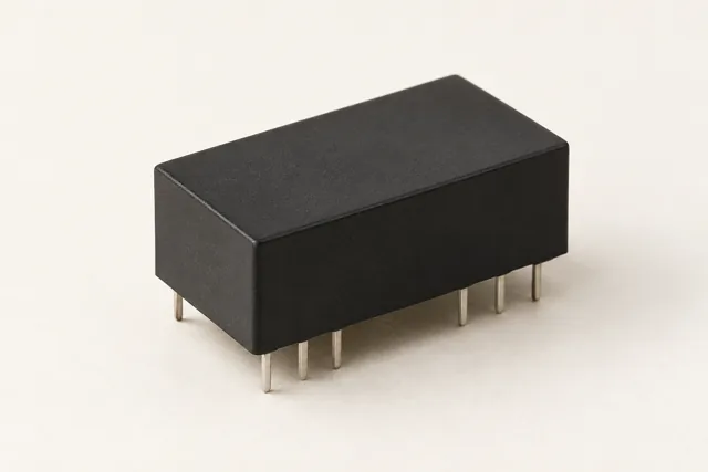
DC-DC conversion
Full input range; required output rails; continuous/peak current; isolation requirement.
Requirements & interfaces ↗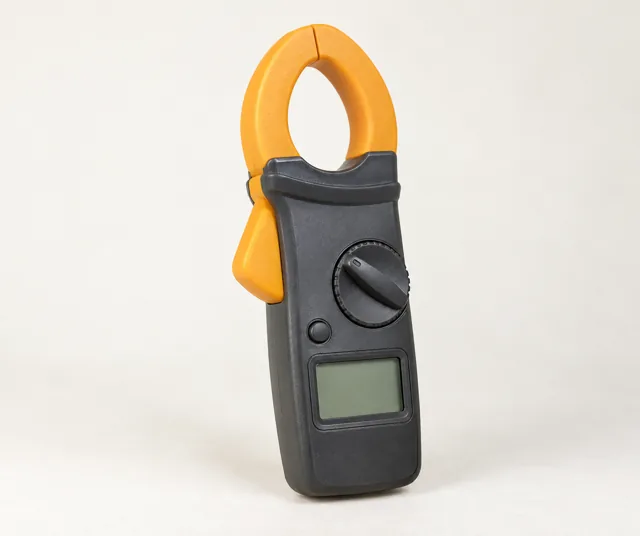
Current measurement
Pack, branch or phase location; current range; bandwidth and accuracy; analog or supported digital output.
Requirements & interfaces ↗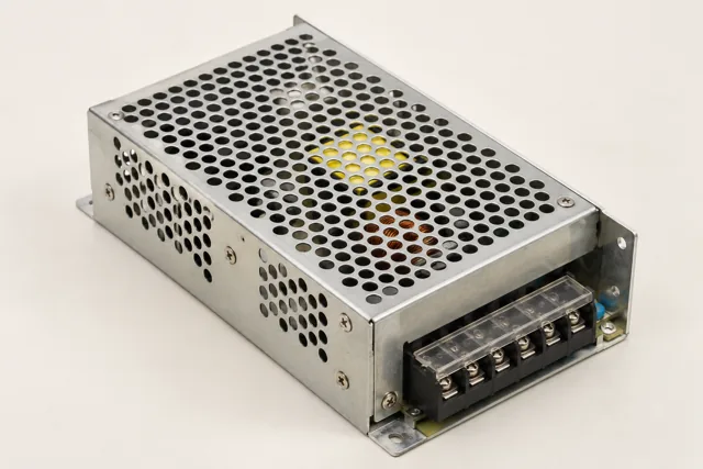
AC-DC — plugged-in single axis
Mains input range; output voltage/current; continuous power; installation and thermal conditions.
Requirements & interfaces ↗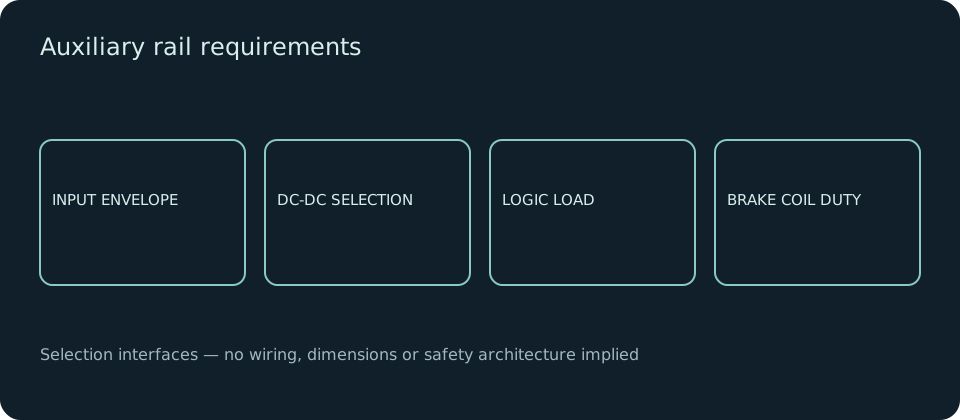
Brake & logic auxiliary rail
Loads requiring a separate rail; voltage/current and startup; shutdown sequence; isolation and retention requirements.
Requirements & interfaces ↗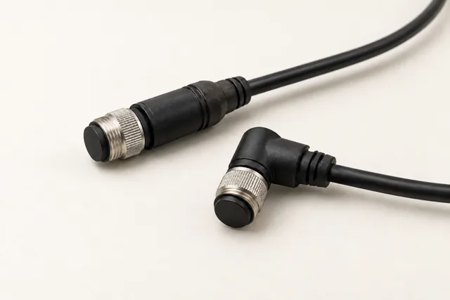
M12 signal assemblies
Both mating halves; pin count and device pinout; required coding and cable; operating exposure.
Requirements & interfaces ↗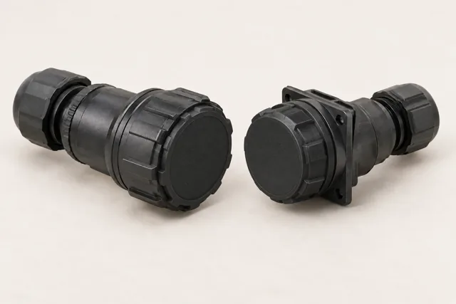
Locked circular power
Operating voltage/current; locking and mating pair; field handling and mating cycles; washdown and cable requirements.
Requirements & interfaces ↗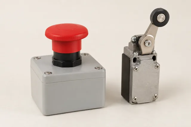
E-stop & enable interfaces
Receiving safety/enable interface; loop voltage and channels; monitoring requirements; reset and restart behavior.
Requirements & interfaces ↗
Cable & drag-chain conditions
Flex cycles and travel; minimum bend radius; torsion where applicable; power/signal routing and exposure.
Requirements & interfaces ↗SUPPLY SCOPE
System context outside the quoted line.
Battery packs · BMS · chargers · LiDAR · safety scanners · cameras · navigation computers · fleet software.
Battery packs, BMS, chargers, navigation computers, LiDAR, safety scanners, cameras and fleet software are outside our quoted component line. We consider only the specified power and connector interfaces to those devices.
COMMERCIAL VEHICLE / ELECTRICAL INTERFACES
Vehicle interfaces use the existing component lines.
These eight interface views lead to motion, power and interconnect requirements. They do not add controllers, batteries, charging equipment or software to the quoted component catalog.
Vehicle controller: power & signal
Supply, enable and signal connectors to the specified controller. The controller and its control software stay with their supplier.
Explore requirements & interfaces ↗Battery input & protection
Define reverse-polarity protection, inrush, disconnect and the loaded voltage range. Cells, battery packs, BMS and chargers are outside the quoted line.
Explore requirements & interfaces ↗Auxiliary power rails
Derive the specified auxiliary rails, such as 12 V or 5 V, from the equipment input through DC-DC conversion. Confirm whether isolation is required separately.
Explore requirements & interfaces ↗Operator switches & indicators
Review electrical switches, indicators and their connections. Display software and operator-interface applications are outside the quoted line.
Explore requirements & interfaces ↗Vehicle network connectors
Review CAN or the specified bus at its defined mating connector. Use M12 A-coded only when the device specifies it; coding alone does not determine the pinout.
Explore requirements & interfaces ↗Diagnostic service connector
Scope the service plug, mating pair and device-defined pinout. Calibration files, diagnostic software, firmware and OTA remain with the controller supplier.
Explore requirements & interfaces ↗Navigation: power & signal boundary
Only the device-specified power and signal interfaces are considered here. Navigation computers, LiDAR, cameras and autonomy software are outside the quoted line.
Explore requirements & interfaces ↗Fleet services: outside quoted line
Hosting, user roles, retention, alerts and software updates are a separate software project. We consider only the power rail and connector feeding an already specified telematics device.
Explore requirements & interfaces ↗